Guide
This document provides some requirements and recommendations for the development of HVAC system templates to be included in the Modelica Buildings Library (MBL). It is primarily intended for developers and therefore contains some detailed implementation guidelines. For a more conceptual presentation of MBL templates, see Gautier (2023).
Interface Class: What Shall Be Declared?
Outside Connectors Needed by Any Derived Class
All outside connectors must be declared within the interface class—with the suitable conditional instance statements.
(Each class extending an interface class shall not declare any outside connector—it may only conditionally remove inherited connectors.)
This ensures the plug-compatibility of each derived class, and implies a fixed connectivity structure for each instantiated subsystem model, allowing these instances to be connected to each other without worrying about the actual configuration of each subsystem. This applies to connecting components within a template, or connecting templates to each other to create a whole-building model.
Details
How does it comply with the Modelica Language Specification?
Type compatibility:
Each reference is checked, whether it is a valid reference, e.g. the referenced object belongs to or is an instance, where all existing conditional declaration expressions evaluate to true|false, or it is a constant in a package.
So checking that the redeclared component is a subtype of the constraining class is done with all the conditional connectors considered present (even if the redeclared component removes them).
How does it differ from interface classes in the Modelica Buildings Library?
Interface classes are usually implemented with the minimum set of connectors (and other variables) and derived classes extend that set, which ensures type compatibility. See for example:
extends Interfaces.TwoPortHeatMassExchanger(...); // Interface class used by the model

Modelica.Blocks.Interfaces.RealInput y(...)       // Additional connector not declared in the interface class
  "Part load ratio";
Modelica.Blocks.Interfaces.RealOutput T(...)      // Additional connector not declared in the interface class
  "Temperature of the fluid";
Modelica.Thermal.HeatTransfer.Interfaces.HeatPort_a heatPort  // Additional connector not declared in the interface class
  "Heat port, can be used to connect to ambient";
Both the Parameter Record and Locally Accessible Design Parameters
The parameter record is for propagation of design and operating parameters across the instance tree.
The local design parameter declarations ensure that a standard set of parameters is available in any template or component, for any configuration.
(For example, an evaporator coil still has mChiWat_flow_nominal defined with a final assignment to 0.)
This way, one can easily compute the sum of a quantity over a set of instances.
(For example, the total CHW flow rate over all terminal units.)
Most of the local design parameters have final assignments to the parameters from the record.
Example
final parameter Modelica.Units.SI.MassFlowRate mAirSup_flow_nominal=
  dat.mAirSup_flow_nominal
  "Supply air mass flow rate"
  annotation (Dialog(group="Nominal condition"));
final parameter Modelica.Units.SI.MassFlowRate mAirRet_flow_nominal=
  dat.mAirRet_flow_nominal
  "Return air mass flow rate"
  annotation (Dialog(group="Nominal condition"));
parameter Modelica.Units.SI.MassFlowRate mChiWat_flow_nominal
  "Total CHW mass flow rate"
  annotation (Dialog(group="Nominal condition"));
parameter Modelica.Units.SI.MassFlowRate mHeaWat_flow_nominal
  "Total HHW mass flow rate"
  annotation (Dialog(group="Nominal condition"));
parameter Modelica.Units.SI.HeatFlowRate QChiWat_flow_nominal
  "Total CHW heat flow rate"
  annotation (Dialog(group="Nominal condition"));
parameter Modelica.Units.SI.HeatFlowRate QHeaWat_flow_nominal
  "Total HHW heat flow rate"
  annotation (Dialog(group="Nominal condition"));
And the derived class:
extends Buildings.Templates.AirHandlersFans.Interfaces.PartialAirHandler(
  ...
  final mChiWat_flow_nominal=if coiCoo.have_sou then dat.coiCoo.mWat_flow_nominal else 0,
  final mHeaWat_flow_nominal=(if coiHeaPre.have_sou then dat.coiHeaPre.mWat_flow_nominal else 0) +
    (if coiHeaReh.have_sou then dat.coiHeaReh.mWat_flow_nominal else 0),
  final QChiWat_flow_nominal=if coiCoo.have_sou then dat.coiCoo.Q_flow_nominal else 0,
  final QHeaWat_flow_nominal=(if coiHeaPre.have_sou then dat.coiHeaPre.Q_flow_nominal else 0) +
    (if coiHeaReh.have_sou then dat.coiHeaReh.Q_flow_nominal else 0));
Both the Configuration Record and Locally Accessible Configuration Parameters
The configuration parameters are declared in the interface class, as is the configuration record cfg which "groups" them into a single object more suitable for propagation.
This record instance is not needed directly within a template class, but rather serves to reduce the number of parameter bindings when using a top-level parameter record (for all HVAC systems) that must access the configuration parameters of each template instance. It can be considered as the "signature" for a given system configuration, accessible within any template.
The instance cfg must be ultimately assigned the final keyword, as it should not be exposed to the user.
Contrary to design and operating parameters, the configuration parameters are propagated (with final bindings) from the component model to the record instance.
Example
replaceable parameter
  Buildings.Templates.AirHandlersFans.Configuration.PartialAirHandler cfg(
  final typ=typ,
  final typFanSup=typFanSup,
  final typFanRel=typFanRel,
  final typFanRet=typFanRet,
  final have_souChiWat=have_souChiWat,
  final have_souHeaWat=have_souHeaWat)
  "Configuration parameters";
parameter Buildings.Templates.AirHandlersFans.Types.Configuration typ
  "Type of system"
  annotation (Evaluate=true, Dialog(group="Configuration"));
parameter Boolean have_porRel=
  typ==Buildings.Templates.AirHandlersFans.Types.Configuration.ExhaustOnly
  "Set to true for relief (exhaust) fluid port"
  annotation (Evaluate=true, Dialog(group="Configuration", enable=false));
parameter Boolean have_souChiWat
  "Set to true if system uses CHW"
  annotation (Evaluate=true, Dialog(group="Configuration"));
parameter Boolean have_souHeaWat
  "Set to true if system uses HHW"
  annotation (Evaluate=true, Dialog(group="Configuration"));
inner parameter Buildings.Templates.Components.Types.Fan typFanSup
  "Type of supply fan"
  annotation (Evaluate=true, Dialog(group="Configuration"));
inner parameter Buildings.Templates.Components.Types.Fan typFanRet
  "Type of return fan"
  annotation (Evaluate=true, Dialog(group="Configuration"));
inner parameter Buildings.Templates.Components.Types.Fan typFanRel
  "Type of relief fan"
  annotation (Evaluate=true, Dialog(group="Configuration"));
And the derived class:
extends Buildings.Templates.AirHandlersFans.Interfaces.PartialAirHandler(
  redeclare final Buildings.Templates.AirHandlersFans.Configuration.VAVMultiZone cfg(
    final typCoiHeaPre=coiHeaPre.typ,
    final typCoiCoo=coiCoo.typ,
    final typCoiHeaReh=coiHeaReh.typ,
    final typValCoiHeaPre=coiHeaPre.typVal,
    final typValCoiCoo=coiCoo.typVal,
    final typValCoiHeaReh=coiHeaReh.typVal,
    final typDamOut=secOutRel.typDamOut,
    final typDamOutMin=secOutRel.typDamOutMin,
    final typDamRet=secOutRel.typDamRet,
    final typDamRel=secOutRel.typDamRel,
    final typSecOut=secOutRel.typSecOut,
    final typCtl=ctl.typ,
    final buiPreCon=ctl.buiPreCon,
    final stdVen=ctl.stdVen), ...);
This allows the top-level parameter record to access all configuration parameters of a VAV instance with a single binding as follows.
outer VAV VAV_1
  "Instance of MZVAV model";
parameter Buildings.Templates.AirHandlersFans.Data.VAVMultiZone dat_VAV_1(
  final cfg=VAV_1.cfg, ...);
Nested Expandable Connectors
The interface class of the main controller must have protected instances of all sub-buses, and these sub-bus instances must be connected to the corresponding variables from the main control bus as follows:
  Buildings.Templates.ChilledWaterPlants.Interfaces.Bus bus
    "Plant control bus";
protected
  Buildings.Templates.Components.Interfaces.Bus busValChiWatChiIso[nChi]
    if typValChiWatChiIso<>Buildings.Templates.Components.Types.Valve.None
    "Chiller CHW isolation valve control bus";
equation
  connect(busValChiWatChiIso, bus.valChiWatChiIso)
This is particularly important in the case of array sub-buses. We avoid pre-declaring these sub-buses in the main bus definition because this would require including structural parameters for the array size inside the bus, and thus binding these parameters for each bus instance. Instead, we use instances of sub-buses in the interface class of the controller and the connect statement connect(bus<Component>, bus.<component>) allows Modelica compilers to assign the correct dimensions to bus.<component> (which is not predeclared in the bus definition).
Components
Replaceable Component
No choicesAllMatching annotation is allowed in the Templates package (to maximize support across various Modelica tools).
Expand into an explicit choices annotation with proper description strings and the following rules.
Systematically use redeclare replaceable in the choices annotation to allow
- further redeclaration by the user,
- visiting the parameter dialog box of the redeclared component (this is Dymola's behavior, although this behavior is automatically enabled if the redeclared component contains replaceable components).
Non-replaceable Component
If a composite component (such as a section) contains replaceable components, or components with configuration parameters that must be exposed, then it must be instantiated with the replaceable keyword so that ctrl-flow generates a parameter dialog for this component, and allows the user to specify the options for the nested components.
This is true even if the type of the composite component is fixed.
In this case, the component is still declared as replaceable, but without any choices annotation (e.g., section secOutRel in Templates/AirHandlersFans/VAVMultiZone.mo).
Section
A composite model that we call section is needed whenever there is a hard constraint on the allowed choices for two replaceable components that are on the same composition level.
Example
In the case of a multiple-zone VAV with an air economizer, a return fan should require a modulating relief damper. However, we cannot bind the redeclaration of the damper component to the redeclaration of the return fan component. So we introduce a section Templates.AirHandlersFans.Components.ReliefReturnSection that contains the two components, so that the whole section component can be redeclared with the proper inside fan and damper components.
The interface class for a section must use the same class for the control bus as the one used by the system template.
This is different from the base components, which have their own class for the control bus, as is implemented in Templates.Components.Interfaces.Bus.
The motivation is to avoid nesting expandable connectors and to allow seamless traversal of the composition levels when connecting signal variables, see for example:
connect(secOutRel.bus, bus);            // secOutRel is a section (instance of OutdoorReliefReturnSection)
connect(ctl.bus, bus);                  // ctl is a controller (instance of G36VAVMultiZone)
connect(damRet.bus, bus.damRet); // connection to the damper bus inside the section
connect(ctl.yRetDamPos, bus.damRet.y); // accessing the damper control variable inside the controller
Main Controller
The template is intended to be used by applications other than Modelica tools, such as ctrl-flow. To be compatible with these applications, the controller implementation must respect the following rules.
Control Section
All blocks that constitute the control sequence of a system are instantiated within a single component within the template.
This component is referred to as the "control section" and is named ctl. It is similar to a section, see for example Templates.AirHandlersFans.Components.Controls.G36VAVMultiZone.
The component ctl is not CDL-compliant due to the following reasons:
- It contains extends and redeclare statements.
- It may include inner and outer declarations.
- This remains true for the VAV templates, which were the first to be developed. However, the most recently developed templates have deprecated the use of inner and outer declarations, with the exception of the requirement stated below.
- Beyond the control section, to reference the configuration parameters from each configuration class prior to class instantiation, it is also necessary to include outer declarations within the top-level data record that stores the control parameter values.
- It uses expandable connectors.
- It may have an initial equation section.
- It employs non-permissible data types, such as
Modelica.Units.SI.**. - It assigns values to parameters using variables from the equipment model, which are outside the CDL scope.
Control Parameters and Binding Equations
In contrast to the CDL implementation of the SOO, we restrict the exposed parameters to the data that are
- scheduled in design documents by the design engineer, or
- provided by the testing, adjusting, and balancing contractor, or
- determined by the control contractor.
See ASHRAE (2021) Section 3 for typical required data.
These parameters are propagated by means of the parameter record.
Control parameters within the control section shall be assigned a value using only binding equations that involve expressions permitted in CDL: see https://obc.lbl.gov/specification/cdl.html#parameter-declaration-and-assigning-of-values-to-parameters.
Control Point Connections
All connect clauses between the control blocks within ctl have a graphical annotation (so there are visible connection lines representing those connections).
Most of the other connect clauses have no graphical annotation — typically the connection to a sensor or actuator signal — as this would overload the diagram view.
Instead, a dedicated section is used at the top of the equation section.
equation
  /* Control point connection - start */
  // Inputs from AHU bus
  connect(bus.pAirSup_rel, ctl.dpDuc);
  connect(bus.TOut, ctl.TOut);
  ...
  // Inputs from terminal bus
  connect(busTer.yReqZonPreRes, reqZonPreRes.u);
  connect(busTer.yReqZonTemRes, reqZonTemRes.u);
  ...
  // Outputs to AHU bus
  connect(ctl.yMinOutDam, bus.damOutMin.y);
  connect(ctl.y1MinOutDam, bus.damOutMin.y1);
  ...
  // Outputs to terminal unit bus
  connect(TAirSupSet.y, busTer.TAirSupSet);
  connect(TAirSup.y, busTer.TAirSup);
  ...
  /* Control point connection - stop */
Note that the control section uses the same class for the control bus as the one used by the system template.
Use the same name for the signal variable and for the component it originates from.
Inside the control section, connections to variables within nested expandable connectors should be done by means of the local instances of sub-buses to guarantee that Modelica compilers assign correct dimensions to these variables. See the example in Gautier (2023) Section 5. See also:
equation
  /* Control point connection - start */
  connect(busChi.y1ChiWatReq, ctl.uChiWatReq);  // as opposed to connect(bus.chi.y1ChiWatReq, ctl.uChiWatReq)
Equipment Status
An ad hoc component has been developed to emulate the equipment status and should be used systematically.
The only exception applies to equipment models (like Fluid.Actuators.Dampers.Exponential)
that already provide a feedback signal as an output (for example y_actual for actuator and mover models).
However, if use_inputFilter=false then y_actual is directly connected to the input signal y, potentially creating an algebraic loop if the control logic uses the equipment status.
Switching to using StatusEmulator instead of y_actual if use_inputFilter=false is being implemented through #3499.
Parameter Record
All design and operating parameters are declared within a Modelica record class. This record is used to
- assign design and operating parameter values for all subcomponents,
- support parameter propagation from a top-level, whole HVAC system parameter record,
- populate the equipment schedule in the UI.
Implementation Rules
Subrecord with Configuration Parameters
Within the parameter record, all configuration parameters are (only) accessible via an instance of the configuration record cfg.
This instance uses the annotation annotation (Dialog(enable=false)) as it should not be exposed to the user—and record classes do not allow for protected elements, and this instance cannot be final as it is overridden.
The final override is debatable and the bindings of record instances containing final parameter assignments appear to be under-specified. As a result, the behavior varies across Modelica tools. And even for a given tool, it varies with the constructs being used (such as inheritance or direct definition). Dymola sometimes (see SRF00860858) triggers a "final overriding" error when a record instance contains final bindings and the record itself is propagated from a higher composition level. OCT never yields a warning.
When instantiated within the interface class, the parameter record uses a binding with the local instance of the configuration record, i.e., dat(cfg=cfg).
Here again, because this binding will be overridden when propagated dat from a top-level whole-building record, the final keyword must not be used in this binding.
Parameter Propagation
Parameter propagation is implemented as follows.
- Configuration parameters are assigned from the component model to the record, and propagated up the instance tree.
- Design and operating parameters are assigned from the record to the component model, and propagated down the instance tree.
The record for the controller section needs to be instantiated (not extended) in the master record because it requires many configuration parameters (such as typFanSup) that have duplicates in the master record.
At the component level, we instantiate the parameter record as dat and bind (with final) local design and operating parameters to the record elements.
Details
This implementation is similar to the one from Fluid.Chillers.ElectricEIR.
However, other classes such as Fluid.Actuators.BaseClasses.PartialTwoWayValve extend the parameter class Fluid.Actuators.BaseClasses.ValveParameters to integrate the parameter definitions in a flat structure.
This allows simpler propagation (only the record is passed in) which is agnostic from the parameter structure of the constraining class (for example mWat_flow_nominal is not defined in Templates.Components.Coils.Interfaces.PartialCoil).
Use Only One Nesting Level
If needed, component records must extend (not instantiate) subcomponent records.
For example in Templates.Components.Coils.Interfaces.Data:
- the class cannot extend
Templates.Components.Valves.Interfaces.Databecause of the colliding declarations oftyp, - so
dpValve_nominalis declared locally and a protected record with the typeTemplates.Components.Valves.Interfaces.Datais constructed to pass in parameters to the valve component.
Exposed Parameters
Design and Operating Parameters
In addition to the configuration parameters, the record contains all design and operating parameters required
- by the sequence of operation for all possible system configurations, see ASHRAE (2021) Section 3,
- for sizing equipment models (most of these parameters are already included in 1.).
Modeling and parameters from the "Advanced" dialog tab shall not be included in this record. The record should be viewed as a digital avatar of the manufacturer’s data sheet for a given system, and as such, should only contain equipment and control parameters that HVAC designers are familiar with.
The set of required parameters depends on the actual system configuration. However, MLS does not allow parameters to be conditionally instantiated. (More precisely, conditional components can only be used in connect statements, which prevents the use of conditional parameters.) As a workaround, we use parameter declarations with
- an
enableannotation, and - an explicit
startattribute.
Details
From the language specification:
If
enable = false, the input field may be disabled and no input can be given.
In our case, if the enable attribute evaluates to false, these parameters are actually not used in the flat equation system — after removing the conditional components with false condition and taking into account all redeclarations. We use the start attribute to provide a "placeholder" value that has no impact whatsoever on the simulation results.
For more details, refer to Section 6.2 and Listing 2 of Gautier (2023).
System Tags
System tags are optional parameters that are not used for simulation but nevertheless included in the parameter record of each template to support future workflow automation (e.g., parameterization of a template by means of an external equipment schedule).
  parameter String id=""
    "System tag"
    annotation (Dialog(tab="Advanced"));
  parameter String id_souChiWat=""
    "CHW supply system tag"
    annotation (Dialog(tab="Advanced", enable=have_souChiWat));
  parameter String id_souHeaWat=""
    "HHW supply system tag"
    annotation (Dialog(tab="Advanced", enable=have_souHeaWat));
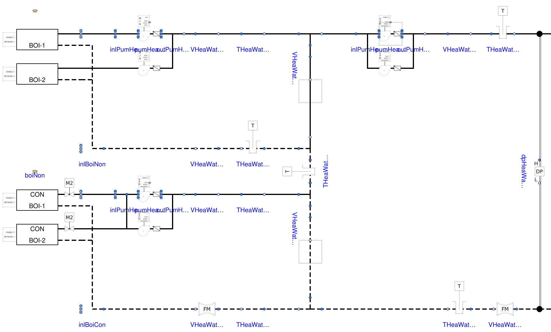
System Schematic
Refer to the specification for the generation of engineering schematics if needed.
Example
Below is an illustration of the kind of schematic (or control diagram) we want to generate, taken from Templates.HeatingPlants.HotWater.Validation.BoilerPlant in branch issue3266_template_HW_plant, using Dymola's feature "Show Component".
Component Icons
Currently the SVG graphics integrated using class annotations such as Icon(graphics={Bitmap(fileName=<svg-file-path>, visible=<boolean-expression>)) are
- not supported by Modelon Impact: ticket open at Modelon#2022042039000931 on the roadmap for the 2023.1 release,
- not fully supported by OMEdit: most likely due to
<boolean-expression>not being evaluated at UI runtime, - entirely supported by Dymola
>=2022.x.
The master SVG document containing all raw icons provided by Taylor Engineering and used in ASHRAE (2021) is currently located at Resources/Images/Templates/Icons.svg.
Those raw icons must be processed as described below for Inkscape >=1.1 before being used in the icon layers of Modelica classes.
Details
The requirements below stem from the following observations.
- The Modelica Language Specification specifies
type DrawingUnit = Real(final unit="mm"). - The default icon layer size in Dymola is mm (
{{-100,-100},{100,100}}). This corresponds to cells in the icon view. So one cell corresponds to mm. - When instantiated, a component has its icon scaled by a factor in the diagram layer. For example, a
Lineobject withthickness=5in the icon layer is rendered as aLineobject withthickness=0.5in the diagram layer. - When
thickness < 0.25, the stroke width remains unchanged in Dymola: so and yield the same stroke width. - It seems that Dymola handles Bitmap objects as squares, i.e., the objects are scaled by the minimum of the
xandydimensions. Having external SVG files with equal height and width makes it easier to position and scale the graphical objects.
- Select object, copy to new file.
- Change stroke color to black and stroke width to mm.
- Account for mm for each grid cell in Dymola icon layer.
- So the default icon layer size of cells in Dymola corresponds to a page size of mm in Inkscape.
- For most of the AHU components, lock width/height ratio and change height to mm.
- For transducers, mm is for the probe, mm is for the sensor casing.
- For polygons, the different segments will typically not be connected together (gap at each corner), so select each segment with
Nodetool and useNodefunctionalities toConvert selected objects to pathJoin selected nodes- For the last corner use
Path/Union
- Text should be in sans-serif with font size of .
- If needed (typically in case of specific text orientation), select text object and transform to path with
Path/Object to Path.
- If needed (typically in case of specific text orientation), select text object and transform to path with
- Set the page size with the same height and width (typically mm) and center icons in the page.
- Save as Inkscape SVG.
Graphical Primitives
In addition to external SVG files, the schematics may use Modelica graphical primitives with the following conventions.
| Equipment | Primitive | Icon layer | Diagram layer |
|---|---|---|---|
| Supply pipe (*) | Line, solid | Thickness | Thickness |
| Return pipe (*) | Line, dashed | Thickness | Thickness |
| Duct wall | Line, solid | Default thickness () | Default thickness () |
| Capillary tube (pressure sensor) | Polygon or rectangle | Default thickness (), width | Default thickness (), width |
| Motor shaft (actuator), connection between sensor and transmitter | Line, solid | Default thickness () | Default thickness () |
(*) This should be specified as a graphical annotation to the corresponding connect statement.
Graphical primitives that need to be pruned to generate the system schematic shall use the annotation visible=viewDiagramAll where viewDiagramAll is declared in the template interface class with:
inner parameter Boolean viewDiagramAll=false
  "Set to true to view all component icons in diagram view"
  annotation (Dialog(tab="Graphics"));
Vendor Specific Annotations
Vendor annotations are either
- hierarchical annotations in the form of
"__ctrlFlow" class-modification, using strict camel case formatting for any argument in the class modification, or - simple annotations in the form of
"__ctrlFlow" "_" IDENT.
Class Annotations
__ctrlFlow(routing="root|template")
In ctrl-flow, the template discovery process relies on a grep for the following hierarchical class annotations:
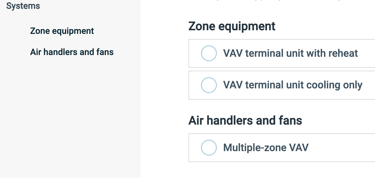
__ctrlFlow(routing="root"): Marks the top-level package containing all templates, e.g.,Buildings.Templates__ctrlFlow(routing="template"): Marks individual template classes, e.g.,Buildings.Templates.AirHandlersFans.VAVMultiZone
All template classes, and all packages between the root package and the template classes are considered as "entry points". This means that the class URI ultimately dictates the explorer tree structure, starting from the "root" package which must be unique inside a library.
So the file arborescence:
Templates
├── AirHandlersFans
│   ├── ...
│   ├── package.mo
│   └── VAVMultiZone.mo       # Contains __ctrlFlow(routing="template")
├── Components
│   └── ...
├── Data
│   ├── AllSystems.mo
│   ├── package.mo
│   └── ...
├── package.mo                # <--- Contains __ctrlFlow(routing="root")
├── package.order
├── Types.mo
├── UsersGuide.mo
└── ZoneEquipment
    ├── ...
    ├── package.mo
    ├── VAVBoxCoolingOnly.mo  # Contains __ctrlFlow(routing="template")
    └── VAVBoxReheat.mo       # Contains __ctrlFlow(routing="template")
yields the following UI objects:
Declaration Annotations
__ctrlFlow(enable=true|false)
Each declaration or extends statement may have a hierarchical annotation "__ctrlFlow" "(" "enable" "=" logical-expression ")" that allows disabling input fields in the ctrl-flow configuration dialog. This is similar to the Modelica annotation Dialog(enable=true|false) but provides additional flexibility and allows disabling all parameter input fields that are brought in by an extends statement.
It takes precedence over the standard annotation Dialog(enable).
Typical use cases include classes from the Modelica Buildings Library that contain definitions of detailed simulation parameters and that are extended to define template components, or package classes used to specify the fluid properties.
Boolean Literal or Expression?
Although only Boolean literals are used in the templates as of commit 675801b669, the expression evaluation engine is invoked when parsing __ctrlFlow(enable...), see https://github.com/lbl-srg/ctrl-flow-dev/blob/e2bb34ca76e0d1ed7413691a89ffd8525e16c750/server/src/parser/parser.ts#L296-L317. So in practice, Boolean expressions could be used.
Code Base
Git Workflow
Each new development should start by branching out from the master branch of the Modelica Buildings Library.
Code Tags
The development of templates usually requires several iterations with the author of the CDL implementation of the SOO. This takes time. Code tags have proven useful in this context.
We adopt the code tags from PEP 350 to reference issues and feature enhancements directly in the Modelica code base. All tags should include one of the tag names below in all caps, followed by the name, e-mail address, or other identifier of the person with the best context about the problem, and the GH issue number if available. We keep it simple and only use:
BUGfor what prevents from translating or simulating a model: should prevent mergingFIXMEfor any problematic code not suitable for production: should prevent merging, include PEP 350TODOunder that code tagHACKmainly for workarounds related to Modelica tools' limitations: reference the ticket number from the Modelica tool provider if availableRFEfor a clearly identified development need (as opposed to an idea)
For example:
// FIXME(AntoineGautier #1913): Should be conditional, depending on have_fanRel.
So we can collect all code tags with:
grep -nER '(^|/(\*|/)|<!--|")\s*(BUG|FIXME|HACK|RFE)' Templates/.